
Latest Products



Contact Us
- No.979, Qingchun Street, Liandu District, Lishui, Zhejiang, China
- admin@gyballscrew.com
- +0578-2950898
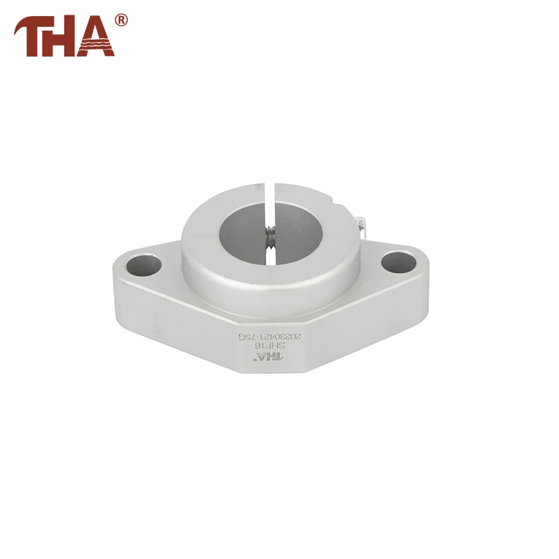


SHF Two Bolt Shaft End Flange
The SHF holds the end of a round guide shaft against a vertical machine plate. Two flange holes secure the support to the plate, while a separate split-bore clamp grips the shaft.
Description
Product Details
The dimensional chart identifies the shaft diameter first, followed by W, L, T, F, G, B and S. These values describe different parts of the installation envelope and should not be replaced by one overall measurement.
W is the full width across the oval flange. B establishes the distance between the two plate holes, while S gives their diameter. L and T describe how far the collar structure extends along the shaft direction. F and G define the vertical envelope around the central bore.
The series includes sixteen metric sizes:
SHF3A, SHF4A, SHF5A, SHF6A, SHF8A, SHF10A, SHF12A, SHF13A, SHF16A, SHF20A, SHF25A, SHF30A, SHF35A, SHF40A, SHF50A and SHF60A.
Product Description
SHF16A provides a useful example of how the chart should be read. It is prepared for a 16 mm shaft and has a 50 mm flange width. Its axial dimensions are L16 and T8, while the mounting-hole spacing B is 40 mm and the hole diameter S is 5.5 mm.
These figures can be transferred directly to the end-plate drawing. The plate designer must still decide whether a separate central clearance hole is required behind the shaft. That opening depends on whether the shaft stops at the collar or continues through the plate.
The mounting holes should be positioned from the shaft axis rather than from an unfinished plate edge. Any cover, frame wall or nearby component must also remain outside the space defined by W, F and the axial projection.
Product Information
| Drawing Reference | Specification |
|---|---|
| Series Format | SHF metric A type |
| Available Models | SHF3A to SHF60A |
| Shaft Diameter Coverage | 3 mm to 60 mm |
| Plate Pattern | Two-hole oval flange |
| Width and Hole References | W B and S |
| Axial References | L and T |
| Vertical References | F and G |
| SHF16A Example | 16 mm bore 50 mm width 40 mm hole spacing and 5.5 mm holes |

FAQ
Does the number in SHF16A identify the shaft diameter?
Yes. SHF16A corresponds to a nominal 16 mm round shaft.
Can the end plate be drilled from the overall flange width?
No. Use dimension B for the hole spacing and dimension S for the individual hole diameter.
Does dimension L represent the machine plate thickness?
No. L belongs to the SHF component itself. Plate thickness is determined separately by the machine design and selected fasteners.
Is a central opening required in the mounting plate?
Only when the shaft or another part must pass through the plate. Its diameter is not defined automatically by the two flange holes.
Can the flange pattern be produced from a customer drawing?
We build to customer drawings under OEM/ODM, and accept orders as small as a single piece for standard sizes.
About Us
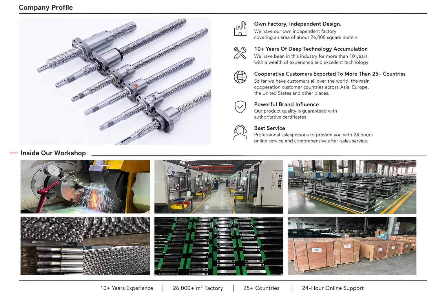
Lishui Guangyuan Industry & Trade Co Ltd supplies metric linear shafts and matching machine-mount components. Standard dimensions and drawing-based parts are available for equipment assembly.

Hot Tags: shf two bolt shaft end flange, Chinashf two bolt shaft end flange suppliers, manufacturers, factory
You Might Also Like


