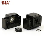
Latest Products



Contact Us
- No.979, Qingchun Street, Liandu District, Lishui, Zhejiang, China
- admin@gyballscrew.com
- +0578-2950898


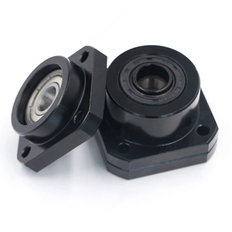
FF Flanged Ball Screw Support
The FF unit fits into a machine end plate through a cylindrical locating spigot, with four flange holes securing the housing to the face. It supports the rotating screw journal while the opposite FK unit establishes axial location.
Description
The end plate becomes the mounting reference
A flange support changes how the screw connects to the machine frame. Instead of placing a bearing block on a horizontal mounting bed, the FF Flanged Ball Screw Support attaches directly to an end face. Its cylindrical spigot enters the plate opening, while the flange seats against the surrounding surface.
Guangyuan's drawing specifies the spigot diameter as D g6. This machined register provides a defined locating interface between the housing and the plate. The four mounting screws secure the flange; the register provides the radial locating feature when used with a suitably specified mating bore. The g6 designation applies to that external diameter, not to the accuracy of the complete screw axis.
Selected dimensions from the FF section of the catalog are listed below. All values are in millimetres.
| Model | Bearing bore d₁ | Locating diameter D g6 | Overall length L | Flange thickness H | Spigot projection F | Bolt-circle diameter PCD |
|---|---|---|---|---|---|---|
| FF6 | 6 | 22 | 10 | 6 | 4 | 28 |
| FF10 | 8 | 28 | 12 | 7 | 5 | 35 |
| FF12 | 10 | 34 | 15 | 7 | 8 | 42 |
| FF15 | 15 | 40 | 17 | 9 | 8 | 50 |
| FF20 | 20 | 57 | 20 | 11 | 9 | 70 |
| FF25 | 25 | 63 | 24 | 14 | 10 | 80 |
| FF30 | 30 | 75 | 27 | 18 | 9 | 95 |
For FF12, the housing occupies 15 mm along the shaft axis: a 7 mm flange and an 8 mm projecting section. The plate design therefore needs to accommodate a 34 mm locating diameter and the space behind the flange. Checking only the visible front face would miss that rear clearance requirement.
The FF Flanged Ball Screw Support also uses counterbored mounting holes. On FF12, the chart specifies four 4.5 mm through holes with 8 mm counterbores, 4 mm deep, on a 42 mm pitch circle. These details define the fastener-head recesses as well as the drilling pattern, which matters when the end plate sits close to a cover or adjacent mechanism.
The bearing carries the supported journal as the screw rotates. It is not the preloaded fixed-end assembly, and the flange mounting does not change that role. Axial positioning remains with the FK side of the installation.
For a recessed end-plate layout, the FF Flanged Ball Screw Support brings the bearing seat and mounting flange into one housing. The useful design check is the complete interface: shaft journal, locating bore, flange seating face and screw-head clearance. Together, these determine whether the unit fits the intended plate without an additional pedestal bracket.


About Us
Guangyuan supplies FK/FF support units and ball screws with ends machined to confirmed drawings. For an assembly quotation, include the shaft-end profiles and the end-plate interface so the required supports can be identified alongside the screw. Drawing-based OEM/ODM requirements are accepted. The minimum order quantity for FF supports is 20 pieces; matching FK units should be specified separately.


Hot Tags: FF Flanged Ball Screw Support, ChinaFF Flanged Ball Screw Support suppliers, manufacturers, factory
You Might Also Like