
1. Root Cause Analysis
On desktop engravers, pick-and-place arms, and light automation frames, a recurring nuisance plagues assembly techs: round guide shafts creeping axial out of their end mounts during rapid reversals. The usual knee-jerk fix in the shop is to crank down hard on the side pinch bolt using an Allen wrench. Ten minutes later, a loud snap echoes from the bench as the split aluminum housing splits right down the stress relief throat.
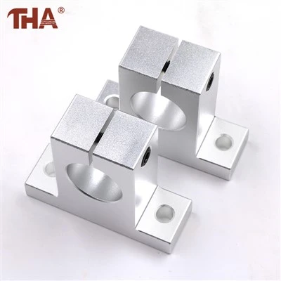
The trouble stems from relying on friction alone against hard-chrome plating without respecting the mechanical limits of cast aluminum alloy. An SK series support block (such as SK12, SK16, or SK20) uses a split clamping collar designed to wrap around a shaft journal. When tech crews over-torque the steel M4 or M5 clamping screw, the localized bending stress at the sharp fillet radius exceeds the ultimate tensile strength of the aluminum body. The block snaps long before it bites into a hard HRC 60 shaft surface.
2. Physical Clamping Comparison
| Mounting Design | Direct Press-Fit Journal | SK Series Split Clamp Bracket |
| Housing Mechanics | Solid Bore Pressed Over Shaft | Split Aluminum Body with Pinch Bolt |
| Assembly Impact | Scuffs Shaft Chrome During Insert | Zero Surface Damage During Positioning |
| Alignment Flexibility | Rigid Location with Zero Play | Allows Axial Slid-In and Easy Height Shimming |
| Maintenance Speed | Requires Puller Tools for Removal | Loosen One Screw to Release Shaft |
Using solid press-fit steel blocks makes shaft adjustment a nightmare on custom frames. The SK series solves this by machining a precision-bored aluminum block with a bottom mounting foot and a vertical slot running from the bore into an internal relief hole. As you snug the pinch screw, the upper collar flexes evenly, closing down around the full circumference of the shaft. This design creates a broad contact area that holds the guide rod securely without needing drive-pin holes or set-screw indentations that mar precision ground surfaces.
3. Practical Mounting Rules for Long-Term Rigidity
Check Base Flatness Before Bolting: Never pull a pair of SK brackets down onto an un-machined extrusion channel with an impact driver. Uneven base contact twists the aluminum body, pinching the shaft at an angle and binding the linear bearing inside the carriage.
Respect Torque Specs on Pinch Screws: Use a calibrated torque driver on the split clamp bolt. M4 bolts on SK10 and SK12 blocks take no more than 2.1 Nm, while M5 bolts on SK16 and SK20 peak at 4.2 Nm. That gives maximum clamping grip without risking stress cracks in the aluminum slot.
Add Mechanical Retaining Rings for High Axial Thrust: If your axis handles heavy impact loads during emergency stops, don't rely entirely on clamping friction. Machine a small circlip groove into the shaft end or add an external split shaft collar snug against the SK block face to take the axial blow.
4. Technical Data Sheet (SK Series Metric Supports)
| Engineering Property | Bracket Specification |
| Model Designation | SK Upright Split Clamp Shaft Support Block |
| Supported Shaft Sizes | Metric Shaft Diameters: SK8, SK10, SK12, SK16, SK20, SK25, SK30 |
| Housing Material | Die-Cast / Extruded High-Strength Aluminum Alloy |
| Surface Treatment | Anodized Surface Coating for Oxidation and Wear Resistance |
| Clamping Hardware | Grade 8.8 / 10.9 Metric Hex Socket Pinch Screws |
| Base Mounting Style | Two-Bolt Flange Foot for Base Plate Securing |


